中文
中文 English
- SABO ELECTRIC
- Industry Socket & Plug
- Maintenance Power Box
- Visible Cut-off Switch
- Distribution Box
- Lighting & Button Box
- SABO INSTRUMENT
- Ultrathin Relay
- Signal Isolator
- Isolated Safety Grid
- Lightning Surge Protector
- Pull Cord & BeltSway Switch
- SABO AUTOMATION
- PLC Control System
- DCS Control System
- Streetlight & Charging-Pile
- Hydrogen fuel cell
- Smart City Internet of Things

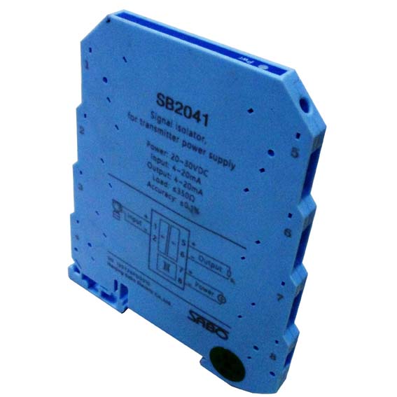
SABO Signal Isolator applicable to the connection between industrial field instruments and control room. It can effectively solve the problem of the industrial automation control system, and ensure the stability and reliability of the system. Products using a new modular design, slim shape of the shell, small size, low power consumption, high conversion accuracy, anti-interference ability. It can be used in the system, such as DCS, PLC and other systems, which are widely used in petroleum, chemical, electric power, steel, machinery, metallurgy, light industry and other industries.
1. Product Features
1) the thickness is only 6.2mm of the ultra-thin structure, uniform shell size.
2) ultra small module circuit, small volume, low power consumption and high accuracy.
3) high speed magnetic isolation.
4) independent DC power supply or loop power supply and 4~20mA current source.
5) screw tight connection, wiring simple.
6) 35mm DIN card standard installation guide.
7) matched signal and field instrument:
Transmitter current input
DC current / voltage signal input and output
AC signal input
Thermocouple, thermal resistance temperature signal input
2. General Technical Parameters
Working power supply: 20 ~ 30VDC
Conventional rated working power supply: 24VDC
Standard accuracy: 0.1%
Temperature drift: 0.015% / C (allowable temperature range)
Response time: < 10ms
Allow the output load current: 4 ~ 20mA, (default)
Isolation capability (input / output / power / meter case and terminal block): AC/1 50Hz min 2500V
Insulation resistance (power / input / output)
Ambient temperature: -20~60 C (run);-40~80 (transportation / storage)
Relative humidity: 5~95%RH (no condensation)
Electromagnetic compatibility: GB/T18268 application requirements (equivalent to IEC61326-1)
Shell material / protection grade: PC (polycarbonate) material of +ABS / IP 20
Dimensions and weight: 6.2 x 84 x 100 (mm); about 50g
Installation: 35mm standard DIN rail type installation
3. Shape Structure
)
4. Installation Wiring
1) installed in a safe place and meet the requirements of the technical specifications of the instrument.
2) it can be mounted on the standard 35mmDIN guide rail. All dimensions of the guide rail shall be in accordance with the standard number: GB/T19334- 2003 standard for the national standard of the TH35-7.5 type guide rail. The standard is equivalent to the international standards of the International Electrical Commission IEC60715-1981.
3) the instrument card is mounted on the standard 35mmDIN guide rail (see the instrument standard guide rail installation diagram), must be stable and strong. The use of the guide rail to prevent the installation of the instrument is installed on the slide and the installation is not stable.
4) can be dense installation.

5. Terminal Connection
1) the wiring diagram of the instrument is connected with the terminal connection diagram.
2) solid core cable wiring used in section 0.5~2.5mm - or multi core cable, strip the cable protection layer of the core length is about 6~8 mm. To ensure that both the cable shield clean, and not damage the cable core.
3) Recommend the use of pre insulated tubular ends, the tubular pre insulated end cover in strip the cable protection layer of the core (see cable core sleeve tubular pre insulated end diagram). And use the crimping pliers tools will be pre tubular insulation head head end (terminal insertion holes in part) pressed into a square or hexagon.The outstanding advantages of using tubular pre insulated end: in a close connection, it can improve the insulation safety and can prevent the cable core bifurcation. Cable connections are also more likely to be inserted into the terminal connection hole.
4) have been prepared by the cable wiring, the cable core (or a pre insulated end head end) connection hole into the terminal, with a screwdriver to tighten the screws on the appropriate terminals (see screw connection diagram).
Next:no!